フォーラム検索:page
-
検索結果
-
トピック: LMK04803の仕様確認3
お世話になります。データシート(SNAS489K –MARCH 2011–REVISED DECEMBER 2014) の記載に関して ご教⽰ください。
P65 8.6.3.2.2 CLKoutX_Y_ADLY
These registers control the analog delay of the clock group CLKoutX_Y. Adding analog delay to the output will
increase the noise floor of the output.
上記に noise floor が増加すると記載があります。相対値で構いませんので情報を頂けますでしょうか。
PLL2の fvcoを使い遅延させる事から PLL2の特性に関係するのではと予想しております。DAC8771のover-rangeとは、
Output Currentが0 mA – 20 mA; 4 mA – 20 mA; ±24 mA
Output Voltageが0 V – 6 V; 0 V – 12 V; ±6 V; ±12 Vのレンジで
Configuration DAC Register (address = 0x04) [reset = 0x0000]の
bit[3:0]のRENGE[3:0]で設定できますでしょうか?
また、Buck-Boost Converterをenableに設定し、
over-rangeで出力することは、可能でしょうか?
2019/4/23までに回答頂けると助かります。大変お世話になっております。
現在、XDS100V2とCCS8.2を使用してソフト書き込み・デバックを進めておりますが、
昨日、急にソフト書き込み・デバッグができなくなってしまいました。
PCの再起動で再びソフト書き込み・デバックができるようになりましたが、
本日、再度同様の現象が起きており、再起動でも問題が解消しません。エラー内容は以下の通りとなります。
配線を確認しておりますが、特に問題ありませんでした。
お手数ですが、対処方法についてご教示願います。C28xx: Trouble Halting Target CPU: (Error -1135 @ 0x0) The debug probe reported an error. Confirm debug probe configuration and connections, reset the debug probe, and retry the operation. (Emulation package 8.0.27.9)
C28xx: Error: (Error -1135 @ 0x0) The debug probe reported an error. Confirm debug probe configuration and connections, reset the debug probe, and retry the operation. (Emulation package 8.0.27.9)
C28xx: Unable to determine target status after 20 attempts
C28xx: Failed to remove the debug state from the target before disconnecting. There may still be breakpoint op-codes embedded in program memory. It is recommended that you reset the emulator before you connect and reload your program before you continue debugging
C28xx: GEL: Error while executing OnTargetConnect(): Could not read register ST1: target is not connected
at (ST1&~(0x0100)) [f28027.gel:283]
at C28x_Mode() [f28027.gel:80]
at OnTargetConnect()-
このトピックは
amatsu1が6 年前に変更しました。
トピック: LMK03328の仕様確認4
お世話になります。データシート(snas668d)の内容に関して 2点ご教示ください。
◆P31 Table 2 の記載
EEPROM page select for soft pin mode or register default mode とあり、soft pin modeでの制御を予定していますが、
その場合 起動時の GPIO2、GPIO3に印加する電位としては (1)VIH =1.4V以上、(2)VIM=0.9V、(3)VIL=0.4V以下、(4)No connection のどの状態とすべきでしょうか。また GPIO2、GPIO3 に印加する電位と pageの関係に関して 教えていただけますでしょうか。
(データシート P32 等を拝見したのですが、6 EEPROM pages という内容しか見つける事ができずで、質問させていただきました。)
◆P32 10.3.2.2 Soft Pin Programming Mode (HW_SW_CTRL = 0) の記載
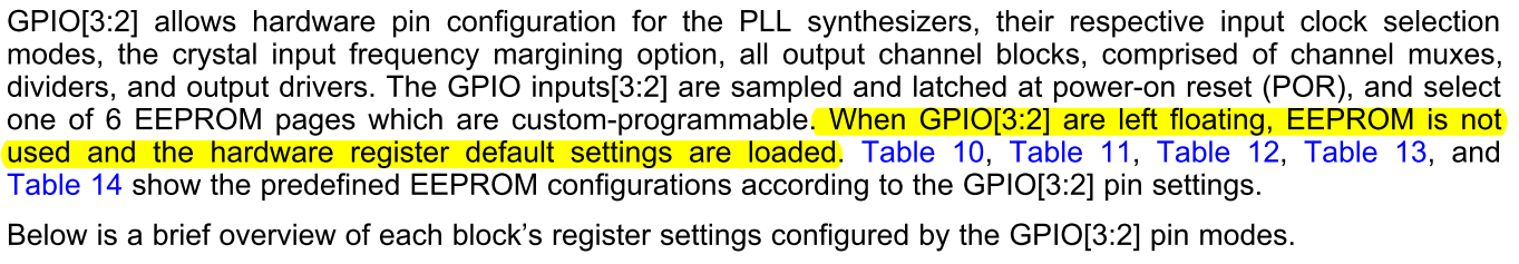
The GPIO inputs[3:2] are sampled and latched at power-on reset (POR), and select one of 6 EEPROM pages which are custom-programmable. When GPIO[3:2] are left floating, EEPROM is not used and the hardware register default settings are loaded. Table 10, Table 11, Table 12, Table 13, and Table 14 show the predefined EEPROM configurations according to the GPIO[3:2] pin settings.
⇒hardware register default settings が指すのは Table 15,16 (Default ROM Contents) となり、またTable 10~14 に記載の内容が EEPROM出荷時の格納値であり Soft Pin Modeで起動した際に loadされるSettingとなりますでしょうか。-
このトピックは
-
このトピックは